Writing a simple x86 BIOS bootloader
This article explains how to write a very simple x86 bootloader script which can be used as the entry point to running a custom operating system. It assumes some knowledge of assembly, but hopefully all required knowledge should be available within this stand-alone article.
Boot Process
When an x86 computer turns on, it executes firmware located in motherboard ROM.
There are two main firmware standards:
- BIOS - "Basic Input/Output System" - Older, simpler, but widely supported
- UEFI - "Unified Extensible Firmware Interface" - Modern, with more features
This article will describe in detail how to write a BIOS bootloader, and does not discuss UEFI.
BIOS Boot
When an x86 cpu boots, the BIOS is loaded from firmware into memory. It performs various operations such as RAM detection, and other hardware detection/initializations - before finally attempting its boot sequence. During the boot sequence, the BIOS attempts to find a boot disk which will load the operating system - via a bootstrap program.
The BIOS generally checks for bootable disks in a specific order. This is potentially user-configurable, known as its bootdisk hierarchy. For instance, checking in the order: floppy disks, CD-ROM drive, then the first hard drive. The BIOS may handle each disk medium differently. For floppy disks the first 512 bytes are read into memory at a specific location, but extra steps may be required for hard drives which contain master boot record information, and CD-ROMs can be loaded entirely into memory and used as a RAM disk. Regardless of medium, the bootloader script will eventually be loaded at address 0x7C00.
As the BIOS iterates through the disk hierarchy it attempts find the first readable 512 bytes (called its boot sector) which ends with the magic number 0xAA55. Once found, the BIOS now gives control to the code which has been copied at address location 0x7C00.
Why the magic number 0xAA55? This the binary equivalent: 101010100101010. This may also be used to determine if your system is big endian or little endian - as it will read as either 0xAA55 or 0x55AA.
Environment
When the BIOS hands over control to your bootloader, the CPU is in 16-bit Real Mode, and the program counter will be running at physical address 0x7c00. Real mode was the only mode before the 80286 Intel processor which introduced protected mode. All processors initially run in real mode, for backwards compatibility purposes.
In real mode you can:
- Access BIOS subroutines
- Access 16 bits
- The CPU can only access 1mb of data
In protected mode you can:
- Use paging, and virtual memory
- Access 32 bits
- Prevent illegal writes to other program's memory that are running at the same time
- Register fault handlers for faulting programs
- Access four privilege levels. Ring 0 being the most unrestricted, and ring 3 being the most restricted
Simple Bootloader example
The following examples are written using the nasm assembler.
apt-get install nasmCreate a new file called boot.asm:
; Simple bootloader example for x86 systems that should print out a simple message to the user

bits 16     ; We're dealing with 16 bit code
org 0x7c00  ; Inform the assembler of the starting location for this code

boot:
    mov si, message ; Point SI register to message
    mov ah, 0x0e    ; Set higher bits to the display character command

.loop:
    lodsb       ; Load the character within the AL register, and increment SI
    cmp al, 0   ; Is the AL register a null byte?
    je halt     ; Jump to halt
    int 0x10    ; Trigger video services interrupt
    jmp .loop   ; Loop again

halt:
    hlt         ; Stop

message:
    db "Howdy!", 0

; Mark the device as bootable
times 510-($-$$) db 0 ; Add any additional zeroes to make 510 bytes in total
dw 0xAA55 ; Write the final 2 bytes as the magic number 0x55aa, remembering x86 little endian
You can compile the above assembly with:
nasm -f bin boot.asm -o boot.binAt the heart of the above bootloader are various calls to the BIOS to request printing characters to the screen. A simplified example of printing to the screen can be shown:
mov ah, 0x0e    ; Set higher bits to the display character command
mov al, 'a'     ; Set the lower bits to our character
int 0x10        ; Call BIOS video service interrupt, which will output 'a'
Emulating x86 hardware
It's possible to write the compiled binary above to a disk, and attach it to a real computer. It can instead be easier to make use of x86 emulators, such as Bochs or Qemu. These emulators will do exactly everything that a real computer would do, but everything is simulated using software instead of hardware.
Qemu
Firstly install qemu:
apt-get install qemu qemu-kvmWithin the same directory as your code:
nasm -f bin boot.asm -o boot.bin
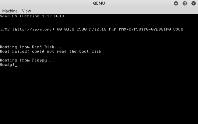
qemu-system-x86_64 -fda boot.bin
After running you should see the simple message appear:
Bochs
Firstly install bochs:
apt-get install bochs bochs-xWithin the same directory as your code, create a file bochsrc.txt:
megs: 32
romimage: file=/usr/share/bochs/BIOS-bochs-latest, address=0xfffe0000
vgaromimage: file=/usr/share/bochs/VGABIOS-lgpl-latest
floppya: 1_44=boot.bin, status=inserted
boot: a
log: bochsout.txt
logprefix: %t-%e-@%i-%d
mouse: enabled=0
display_library: x, options="gui_debug"
Now you can run:
nasm -f bin boot.asm -o boot.bin
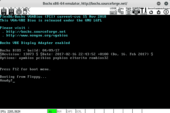
bochs
After running you should see the simple message appear:
Entering protected mode
To enter protected mode you must:
- Register 3 entries in the GDT (Global Descriptor Table)
- null descriptor
- code segment descriptor
- data segment descriptor
- Set the protected mode bit within the control register,
CR0 - Enable the A20 line, or addressing line 20, so that the CPU can access beyond 1mb of data
The lgdt instruction takes a pointer to a structure in memory that is composed of two parts:
- size (2 bytes)
- offset (4 bytes)
Each entry within the GDT is 8-bytes. A simple overview can be found on the osdev wiki - Global Descriptor Table
x86/nasm Cheat sheet
Register names
- Accumulator Register (AX)
- Counter Register (CX)
- Data Register (DX)
- Base Register (DX)
- Stack Pointer (SP)
- Stack base Pointer (BP)
- Source Index (SI)
- Destination Index (DI)
Global Descriptor Table
- Supplied by the kernel
- Defines the various memory segments, what their size is, what they can access, what level they are
Interrupt Descriptor Table
- Supplied by the kernel
- Used to map interrupt vectors to functions, which handle events. i.e. Keydown
String instructions
- The first three letters specify what the instruction, the suffix
Sstands for String - MOVS, LODS, STOS, CMPS, SCAS. - LOD - Load data from the string pointed to ESI into EAX
- STO - Store data from EAX into the string pointed to by EDI
- SCA - Scans the data in the string pointed to by EDI to EAX
- ESI and DSI are incremented if the direction flag is set, otherwise decremented
BIOS Calls
- Generally set the AH register
- Call the required interrupt, i.e.
int 0x10 - No longer available in protected mode
Labels
- A global label is defined as
name: - A label prefixed with
.is local to the above global label, i.e..loop
Pseudo-instructions
- DB, DW, DD, DQ, DT, DO, DY and DZ declare initialized data in the output file.
$evaluates to the assembly position at the beginning of the line containing the expression$$evaluates to the beginning of the current section; so you can tell how far into the section you are by using($-$$)

